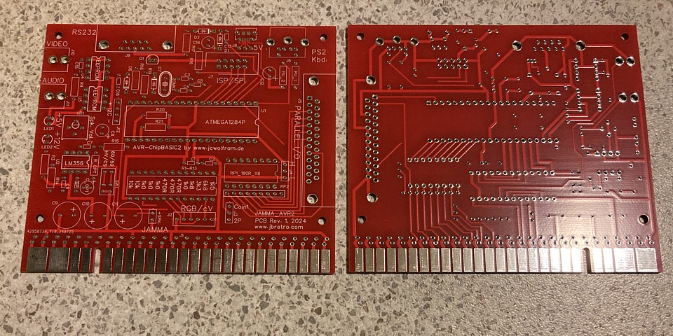
JAMMA_AVR2 PCB project
Here's another retro computing project, with a bit of a twist. It's not a replica of a vintage computer, this one is based on modern hardware but contains all the elements of an early home computer: programmable in BASIC, RS232 connectivity, standard definition analog (greyscale) composite video or 16 colour RGB.
The system is AVR-ChipBasic2 which was developed by Joerg Wolfram between 2006 and 2015 to run on a single ATMega644 microcontroller IC with minimal, mostly passive supporting electronics (see link below). A tiny, standalone computer kit based upon the same firmware operating system and similar hardware was also produced as recently as 2023, known as the CB2 Micro by sv3ora (see link also below)
Both of the systems above feature analog RGB colour graphics using a SCART interface which was popular in Europe but seldom seen in Australia so it seems worthwhile to create a new PCB for the system with an alternate RGB interface. Although I have a couple of CRT TVs (and one LCD TV) which include a SCART input I mainly use these for consoles and for testing arcade PCBs on the test bench. It occurs to me that the AVR system would also work with an early RGB computer monitor (Commodore 1084 etc.) or even a standard resolution arcade monitor.
As I've already resolved to design a new PCB for the system, why not add a JAMMA standard edge connector to one side for power input, speaker out and RGB/Sync to connect to an arcade monitor or even run within a JAMMA wired arcade cabinet? I can also include provision to read some of the JAMMA control inputs via the system's parallel port so that games or other programs could use input from joystick and buttons.
So far so good, the only problem is I'm not up to speed with any current PCB design software and usually just build one-off projects on prototype board. This one requires connectors with special footprints as well as the JAMMA style edge connector so is not suited to stripboard construction. Apart from that, designing a PCB will allow multiple boards to be produced rather than just one prototype.
The circuit design is straight from the jcwolfram.de site (link below) so it is only the PCB layout which I'm designing myself. My thanks to Joerg Wolfram for the software design as well as hardware circuit examples. Beginning with the minimal circuit I have gradually found space on the PCB to accommodate many of the optional components and features shown in the examples on his 'hardware' page.
The PCB itself begins as a blank canvas, its dimensions determined by a 56 pin (2 x 28 way) JAMMA edge connector along one side which gives an overall length around 115mm. In the other direction I've set a nominal size of 99mm as I believe 100mm or more in either dimension may cause a jump in price with some PCB manufacturers. If I can fit the required components within that space there will be no need to go beyond that size anyway.
The recommended process for using the PCB design tools (I'm using EasyEDA in this instance) is to draw the circuit diagram, assigning component numbers and interconnections then transfer that to a PCB workspace using included (or created) PCB footprints for each device. Then the component footprints are arranged on the PCB workspace and interconnections routed automatically using a set of design rules for track width etc. That is usually followed by editing where required to address any routing problems or track interference issues.
I can see how this method, especially for complex circuits with many interconnections would make the process quicker and simpler but for such a small circuit with one main component and, being used to manually laying out circuits on prototype board (using graph paper!) it seems easier to place the component footprints onto the PCB workspace and route the connections manually. Next time I will try the other approach, with a larger circuit...
Designing a PCB for the AVR-ChipBasic2 circuit was a great learning experience. I made (and hopefully corrected) a number of beginner errors, since receiving the first batch of PCBs I've noticed a couple of incorrectly marked components on the silk screen layer but hopefully the connections will be correct and the boards useable without needing to go straight to Revision 2.
There are just a couple of minor alterations to the circuit to provide for JAMMA connection including red and yellow LEDs to indicate the presence of +5V and +12V power supply rails, the +12V if present powers an LM386 low power audio amplifier to provide a speaker output with trimpot for volume control. The 8 bit parallel I/O signals have also been routed to Player 1 control inputs on the JAMMA connector and provision added for a bank of pullup resistors to suit the normally open, common ground control panel switches.
The only surface mount component which I've added to the PCB is a micro USB socket so the board can be powered from a common USB phone supply when not connected to JAMMA wiring. As the PCB has not been tested I will populate the circuit in stages beginning with the minimal hardware to operate the ATmega644PA (or 1284P) microcontroller with 20MHz crystal, PS2 keyboard port, AV composite (grey scale) video and low level audio outputs.
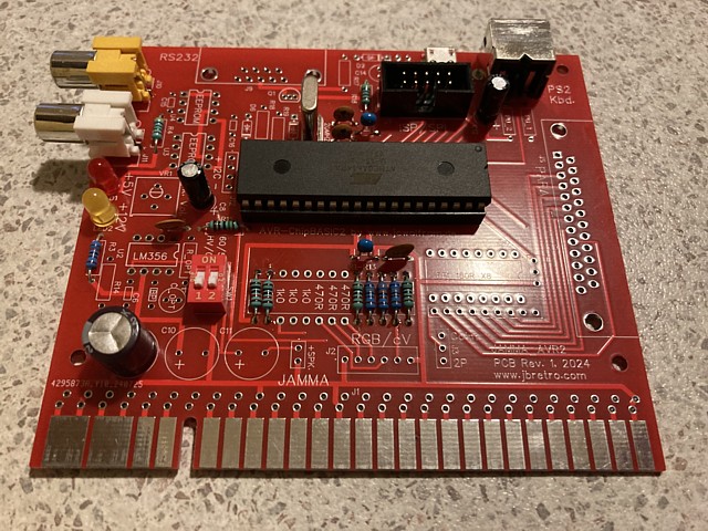
I've provided a footprint for a 2 way DIP switch to select 50Hz / 60Hz video standard and combined or separate Horizontal / Vertical sync (combined sync is always used at present). Alternatively a 2x2 pin header can be fitted instead of the DIP switch and jumpers used to select 60Hz video or separate sync.
The other connection initially included is the 10 pin boxed header, SPI connection for programming the Microcontroller operating system. In this case I've found that my TL866 EPROM programmer can also handle the ATmega644PA (or 1284P) ICs so will preinstall the software before fitting the IC to its 40 pin socket on the PCB.
Having done that and powering on with a USB power supply I get - nothing. No sync on the composite input of my NEC TV monitor. As usual I have my oscilloscope handy and viewing the video output there is a signal with what look like sync pulses and even some video information but the frequencies seem completely wrong. Expecting horizontal sync to be around 15kHz, the signal I'm viewing looks more like just a few hundred Hertz.
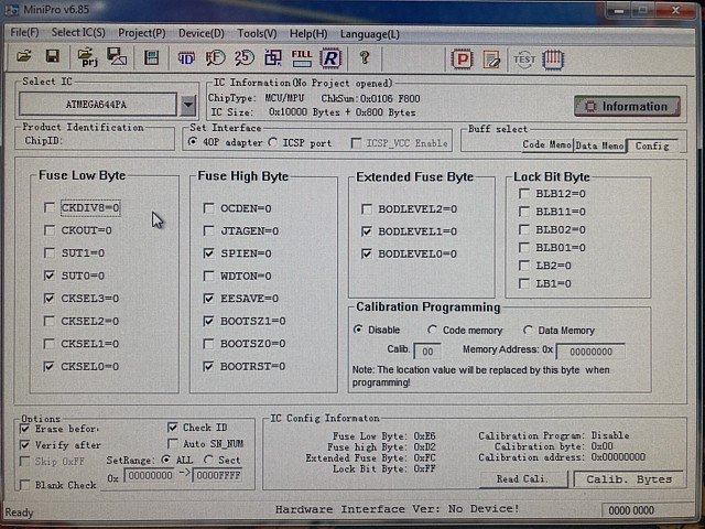
After some reading I learn that the ATmega ICs are highly configurable with options for internal or external crystal oscillator and clock dividers, selected by some configuration bytes which must also be correctly set when programming. Another attempt, this time setting the recommended configuration into the config programming tab gives a result. Returning the micro controller IC to the PCB, powering on produces the startup dialog and pressing space bar takes us to the desktop screen.
Now we're getting somewhere! The system runs and responds to keyboard input although the 'Y' and 'Z' keys are reversed for the 'DE' keyboard layout (and some other differences) compared to 'US' which is also the standard keyboard layout for Australia. There is a binary program which will change the default layout from 'DE' to 'US' so this is the first issue which needs to be addressed by loading, then running the 'kbd_us.bin' program.
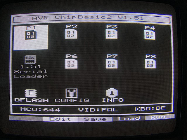
There are 8 slots for programs, either BASIC or binary and the only occupied slot, P5 contains the serial loader program which is used to load or save programs via RS232 to an external computer running terminal software. So the logical next step is to populate the part of this PCB which contains the components for the serial interface.
The RS232 standard which has its origins in the era of electro mechanical teletype machines, specifies a negative and positive Voltage for its 'mark' and 'space' ( 1 or 0 ) states. Although some more recent devices will accept 0 - 5V TTL levels a correct signal should have a range of -3V to +3V or more. To create a negative Voltage the AVR circuit includes a 'charge pump' using an oscillator output from the ATmega IC via 2 diodes and capacitors to create a negative supply of about -4 Volts.
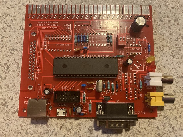
In this photo I've added all of the components between the micro controller and DB9 serial interface connector. It's also necessary to select the 'config' page from the desktop screen, set Serial speed to 2400 Bps, Line end to CR+LF (for Windows systems), Serial In/Out to simple and Serial Input to PD1. The terminal software at the computer end should be set for 2400 Baud, 8 bits, no parity, 2 stop bits and no flow control.
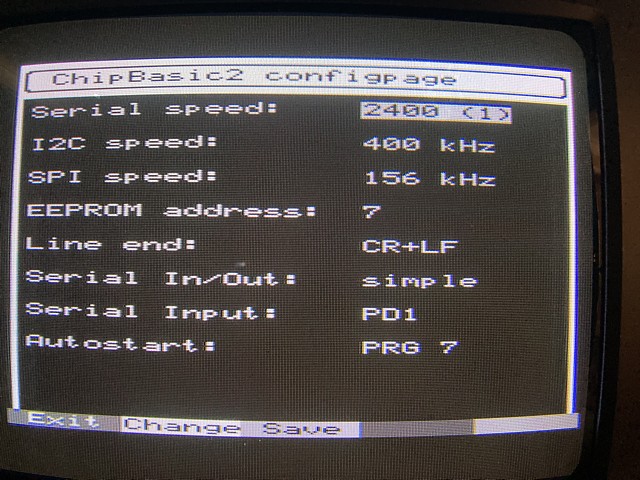
Having made those settings and powering the PCB on the serial loader program attempts to connect to the terminal; it appears to be receiving keystrokes from the terminal (S to request status, Q to quit etc.) but the terminal does not seem to be receiving data from the AVR circuit. Checking the serial port Tx output with my oscilloscope I'm expecting to see a signal which ranges between positive and negative Voltages but the negative component does not appear to be present.
When I exit the serial loader program, pressing space then escape to return to the desktop screen the charge pump circuit appears to run correctly but when the serial loader program runs the oscillator output which is required to generate the negative Voltage is idle. It appears that may be a bug in this version of the operating system so I will try an alternate method of loading the program file from the desktop screen, selecting program slot P1 then CTRL and F3 to receive the program via the serial port.
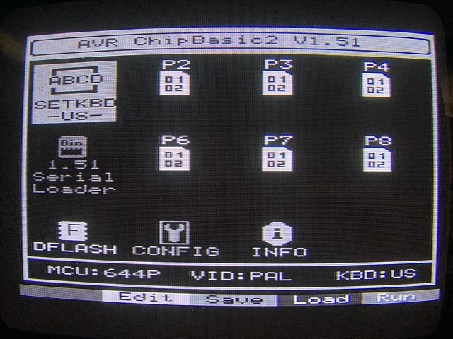
That works fine and the SETKBD-US- program now occupies program space P1. Pressing F4 to run the program changes the default keyboard layout to US. The program only needs to be run a single time as the default layout has been updated so having done that the program can be removed by pressing CTRL and F4 to free up program slot P1 for another program.
To create a new program the editor can be opened by pressing F1 and BASIC commands typed in but for the moment I'll try loading one of the example programs from the AVR project page, saving the program as a text file then receiving that via the RS232 terminal by pressing CTRL and F3 within the program editor screen. The program loads, can be saved to the current slot by pressing F2 and run by pressing F4.
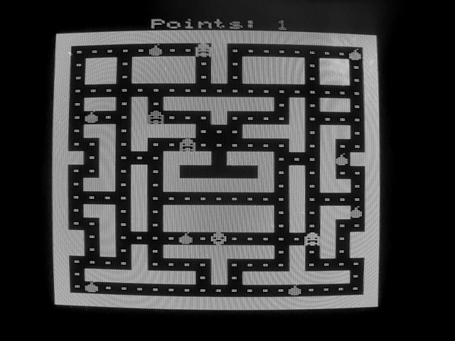
This program is 'Eatman', a pacman style game and a good example of the system capability as it uses the full program space, about 3k Bytes per program slot. It may be possible to accommodate larger, more complex programs by incorporating cross-program subroutines which are reportedly possible within the AVR-Chipbasic2 operating system.
With a small edit to the BASIC program it should be possible to adapt the game to accept input from JAMMA joystick and buttons rather than keyboard but first, let's add the few components to see the system in colour rather than shades of grey.
My PCB for the AVR-Chipbasic2 computer is working with no major issues so far. The system boots up, accepts input from keyboard, loads programs via its RS232 interface which run with grey scale graphics and sound. The next section of the PCB to assemble and test is the RGB 16 colour output. There aren't many components to add, just some resistors as RGB video is already present at the outputs of the micro controller IC.
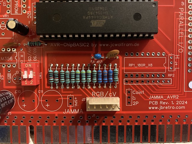
In addition to the R, G, B and Sync contacts on the JAMMA edge connector I've placed a 6 pin header for RGB video to suit a 15kHz computer monitor or SCART TV. The main difference between the signals at those points is the sync. For a SCART TV there is no separate input for sync, it uses the composite video input as the sync source for an RGB signal so the sync level only needs to be about 0.3 Volts.
For the JAMMA interface an arcade monitor would normally be connected, just the combined Horizontal and Vertical sync pulses are used and a higher level is also ideal. In this case I have just taken the signal from U1 pin 19 but with hindsight, should have added some resistance between that point and the sync contact on the JAMMA connector. Although the direct connection would work it doesn't provide any protection for the Micro controller IC in the case of a short circuit on the video cabling etc.
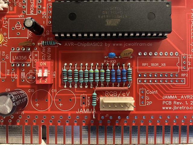
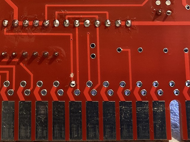
So I'm adding a resistor between the IC and the JAMMA sync output, at least 470 Ohms should be OK but I will try 1k Ohm, hopefully the sync signal will still be sufficient for an arcade monitor. The resistor could be fitted to the solder side of the PCB but I've placed it on the component side to remind me, to incorporate that into any future revision of the PCB. I've also cut the original track on the solder side just before the sync contact on the JAMMA connector.
OK, having done that it's time to see the results. I'm using a cable connected to the 6 pin header initially with the RGB input of my NEC TV monitor, the next step will be to test the JAMMA connections. It looks great, the desktop screen springs to life with glorious, 4 bit colour.
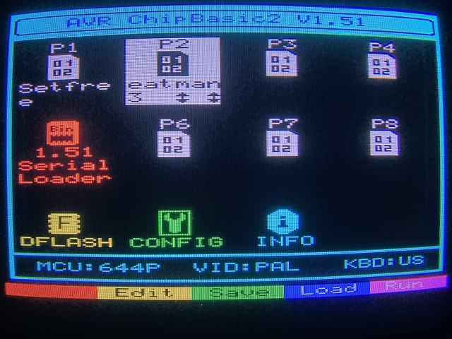
With bright colours, the function key assignments along the bottom of the desktop screen stand out nicely. The 5 coloured labels represent Escape and F1 - F4 keys, holding the CTRL key provides a second set of functions for the keys. Adding labels to the keyboard with corresponding colours for the 5 softkeys would help to access the functions easily.
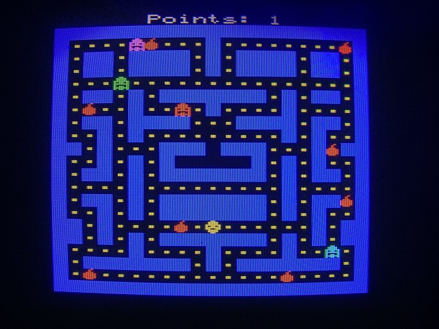
Above is the Eatman game, now showing in colour. There was an issue loading the game from the terminal via RS232 with some incorrect characters received. I think the ANSI formatting of the text file may have been the cause so need to resolve that, meanwhile I just edited the program to correct the errors and saved the changes.
Apart from the example programs on the jcwolfram.de site there are several games and programs available on the qrp.gr site (links for both below) Thanks to sv3ora for the software resources on that site including the original 'setfree' game below.
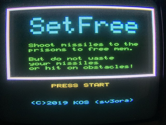
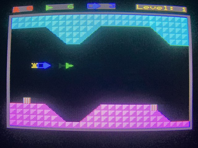
This one is a horizontal scrolling shooter with a Defender / Scramble vibe. The game is fairly minimal compared to arcade versions but another good example of the capabilities (and limitations) of the AVR ChipBasic system. Pretty impressive for a micro controller IC which was never intended to operate as a standalone system, running BASIC.
The next step will be to populate the PCBs parallel I/O section and test the JAMMA interface.
My first attempt at designing a PCB using EasyEDA, for the AVR Chipbasic2 Micro computer appears to be a success. The core system is up and running, all that remains is to populate the peripheral sections of the PCB and test the various ins and outs.
The parallel I/O uses a bank of 8 x 180 Ohm resistors for current limiting to protect the outputs of the ATmega IC and a DB25 socket connector which was the LPT standard printer interface prior to USB. I don't have a parallel printer to test it with at present but fitted the connector anyway, you never know...
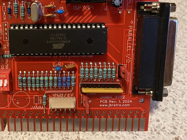
My main reason for adding the resistors is to utilise the 8 bit parallel inputs to detect switch closures on the JAMMA interface for player controls. I've routed bits 7..0 to Player 1 coin, start, Joystick up, down, left, right, buttons 1 and 2. As an alternative to detecting a coin I've included a header so bit 7 can be connected to the 2 player start switch via a jumper link.
To turn a switch closure (to ground as per the JAMMA standard) into a logic level transition a pullup resistor is required for each bit. I've included the footprint for a 9 pin, 8 x 10k Ohm resistor network and routed the common pin to another header so the resistors can be configured either as pull ups or terminations to ground.
I chose quite a high resistance value so the pull up resistors would hopefully not interfere with the data if the parallel data bits are used as outputs. as an extra measure I'll fit a socket for the resistor network so it can be unplugged if required. The pins on the resistor network are flat and not very sturdy so instead of using a turned pin socket strip I'll use a dual wipe 18 pin IC socket which has been cut in half.
Connecting the PCB, this time to my JAMMA bench test lead rather than USB power supply and separate RGB cable, the board powers up as expected. Both +5 and +12V LEDs illuminate although the +12V supply is otherwise unused as yet. To test the JAMMA control inputs via parallel I/O I'll just write a minimal program, saving it to the empty position P3.
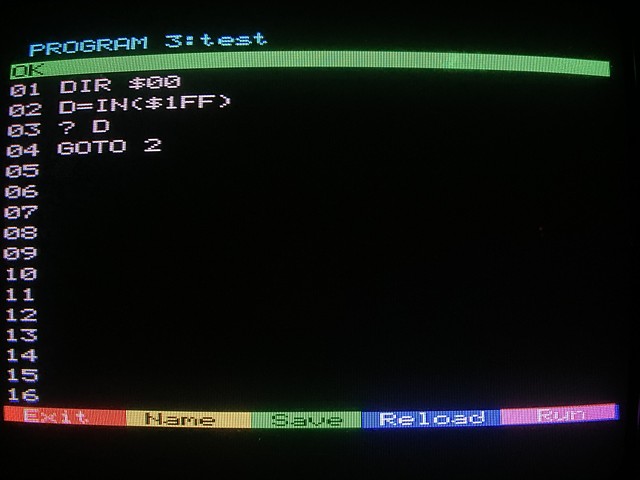
In this system DIR stands for DIRection and $00 sets all bits as inputs. the IN statement can read individual or grouped bits, $1FF selects the full byte. The program runs, just displaying the result on screen in a continuous loop, scrolling as each new result is added. Testing each input and combinations the result changes from 255 for all inputs open through to 0 for all closed.
Each input carries a binary value from 1 for bit 0 (P1 button 2) to 128 for bit 7 (Coin1 / 2P start) - all work as expected with no wires crossed. Pressing CTRL-C on the keyboard exits the program. At this stage that is enough just to confirm the inputs are working, later I'll attempt to adapt some of the example programs to use joystick / button inputs and eventually write some new programs which can be navigated using JAMMA controls rather than keyboard.
Next we'll move on to populate another section of the PCB, for the speaker output. This utilises an LM386 low power amplifier IC with minimal external components, a 10k trimpot for volume control and Electrolytic capacitors for +12V supply filtering and output coupling. In addition to the JAMMA connections I've included a 2 pin header for speaker output.
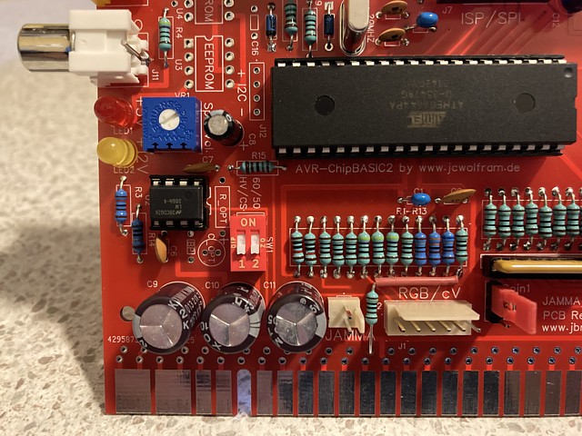
The circuit is straight from the LM386 datasheet, I've included footprints for additional components to increase the amplifier gain but in practice they are not required, the nominal gain of 20 for the basic circuit is ample. At normal level the sound is fine but turning the volume up there is a noticeable hum which doesn't appear to be coming from the power supply, more likely crosstalk from the video circuit.
I'll need to investigate that and see if I can find a way to reduce the hum on the speaker output but for the moment it is OK. I did attempt to avoid any ground loops on the PCB, using a separate ground path for the audio circuit. To see if it makes the symptom better or worse I try linking the audio and video ground tracks together but it makes no noticeable change so I'm fairly sure the hum is not a supply or grounding issue.
The only part of the circuit left to populate is the I2C bus connection and on board EEPROM positions so we'll add those now, finishing the build process. The ATmega644PA and 1284P have some internal EEPROM space where data such as high score tables can be saved but using their I2C bus external serial devices and EEPROMs can be accessed. I've used the circuit examples provided on the jcwolfram.de site to include positions for two serial EEPROMs on board.
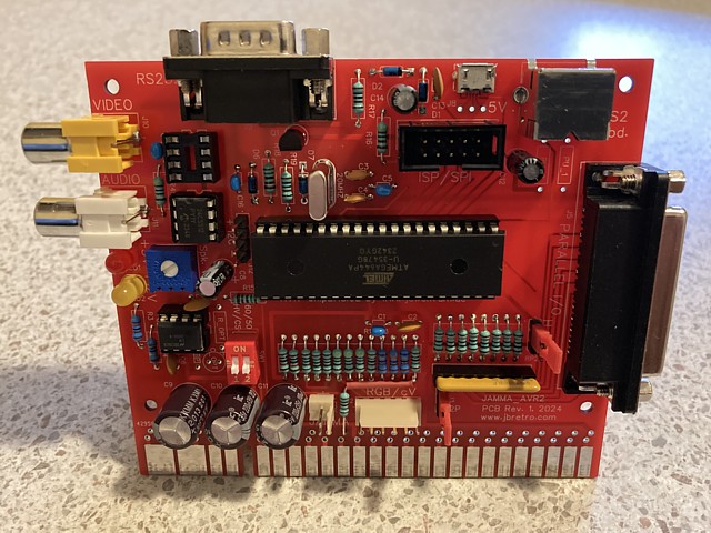
The serial EEPROMs can be type 24C64 to 24C512 and I've initially fitted one 24C512, 64k Byte EEPROM to the position with address 0, the empty socket is address 1. The EEPROMs can contain data rather than program information and are accessed using the XPOKE and XPEEK statements. They could also be preprogrammed with data and, with relatively large amounts of storage I can imagine these containing large arrays and even pre-rendered bitmap data which can be transferred to screen within a simple program routine.
At this stage I'm not familiar enough with the specific version of BASIC used by the system to properly utilise the resources but some initial ideas include a program to generate simple test patterns on screen, using a menu selection controlled by joystick and buttons. Such a program could be set to autoload on startup, alleviating the need for a connected keyboard. Most of these useful patterns are simple combinations of geometric lines, shapes and colours which could be easily produced by a basic program or even loaded directly from EEPROM.
So with the assembly complete the PCB appears to be working correctly, the next stage is to learn the finer points of the AVR-Chipbasic2 programming language and write that test program, maybe some simple arcade style games.
I've assembled and tested my first PCB design which incorporates a JAMMA standard edge connector with the open source AVR Chipbasic2 computer (a link to the original project page for that system is included below). The system is up and running, basic checks of the input and output interfaces including the JAMMA standard video output and control inputs show all working as expected.
It's time to learn the specifics of the BASIC programming language included with the Chipbasic2 system, there is a complete BASIC reference as well several example programs contained within the linked pages below. To begin with I'll try a simple exercise to load some of the mini game example programs and edit the BASIC commands to replace keyboard control inputs with joystick and button controls via the JAMMA / Parallel input port.
That turns out to be pretty straightforward, replacing KEY( ) statements with IN( ) commands where appropriate so the next step is to attempt to create a new program from scratch. My initial thought was to write a test program to use in a JAMMA wired system which could generate RGB test patterns as well as check control inputs, speakers etc.
Test patterns are fairly straightforward being composed of geometric lines, shapes and colours and a simple menu system would allow the program to be controlled by joystick and buttons without the need for a connected keyboard. The system can be set to autorun one program on startup.
With each program space limited to 95 lines of BASIC code I thought the menu as well as the routines to draw the patterns wouldn't fit into a single program slot so I began writing two separate programs, one to draw the patterns and then effectively do a screen dump to the on board serial EEPROM and a second program to create a menu and then transfer the selected pattern from EEPROM to screen.
Although each BASIC program space is only about 3k Bytes one 8 pin serial EEPROM can contain up to 64k of data, ideal for complete graphic images. As it turned out with a bit of trimming the entire program could be squeezed into one slot anyway so the patterns can be selected from the menu and generated on the fly. There was just enough room at the end to add a simple button test which plays a unique tone for each of 8 control inputs.
I've included a video below of the first version running on my test bench RGB monitor. I selected 60Hz as most standard definition arcade monitors run at that rate though my PAL TV/ monitor isn't exactly set up for that standard. The same program will also run at PAL / 50Hz frequency, with an increased border area.
Being written in Basic it's quite simple to add or change the program to suit a specific requirement. I'll attach a text copy of my Test Pattern Generator program here to show the very concise (and fairly easy to learn) version of BASIC employed by the system. There is also a version of the program which is operated by keyboard rather than JAMMA control inputs and should be useable with the original AVR Chipbasic2 and CB2 Micro systems.
tpg_jamma.txt JAMMA Test Pattern Generator v1 BASIC program listing
tpg_rgb.txt RGB Test Pattern Generator v1 BASIC program listing
Here's a little update on the JAMMA_AVR2 Retro computer / test PCB project. I mention the term 'test PCB' as major inspirations for combining the micro computer circuit with a JAMMA edge connector were the JAMMA 'test PCBs' of the 1990's which were included with Japanese 'candy cabs' so they could be sold as complete working machines.
I became fascinated by these tiny games when I picked up a Sega Dottori Kun PCB a while back and did some research to understand why such minimal, 70's style games were produced well into the 1990s. Since then I have also picked up a working example of Taito's 'Mini Vader' test PCB. On the left, Sega Dottori Kun. Taito Mini Vaders on the right and my JAMMA_AVR2 PCB, centre of photo.
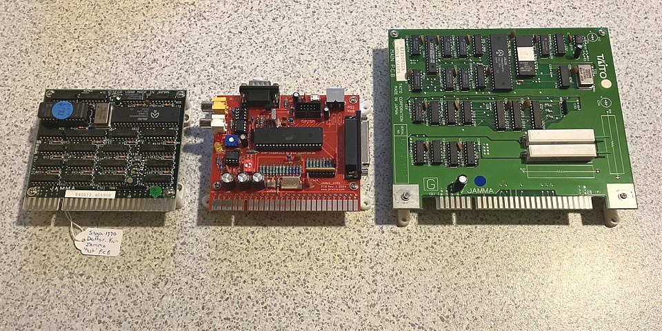
Although they were dubbed test PCBs the little boards included very few test functions at all and the included game was so minimal it barely met the letter of the law which required the machines to be sold as complete and working. Realising their unused potential I wrote a ROM 'hack' for Dottori Kun to produce some monitor test patterns as well as a button test but the included hardware is also very limited with low resolution, black and white graphics and no sound whatsoever.
Dottori Kun does have some ability to change colours via a RGB colour palette, at best this could produce a 'space invaders' style colour overlay to the monochrome graphics but this would have to be carefully timed within the program to produce stable colours at various points on screen while Mini Vaders has no colour ability at all, the three colour outputs being identical. Both are Z80 based so can only be programmed in machine code or z80 assembly language.
The PCB which I've produced is based around the AVR Chipbasic2 operating system by Joerg Wolfram so is programmable in BASIC with several graphics modes and sound / sequencing ability. Although there is considerable overhead running BASIC the MCU clocks along at 20MHz compared to 3 or 4 MHz for the two Z80 based PCBs.
My first revision PCB works well, so far I have written a BASIC program to produce some 'proper' monitor test patterns as well as a simple button / sound test. Since producing the initial PCB I've imagined some enhancements and have come up with a second revision to include some additional features, squeezing a few extra components onto the already busy PCB layout.
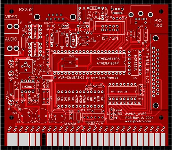
The main changes from the Rev. 1 PCB are; *Some silk screened component designations corrected.
*A reset button added. I found an easier way to restart the MCU than power cycling the PCB was to ground the reset line at the ISP header. To simplify the process I've added a footprint for a tactile switch on the PCB.
*A third LED added to indicate if the -5V supply is present on the JAMMA connector and if so, that Voltage is used to supply the -V for the RS232 interface via a diode and a couple of smoothing capacitors. If the -5V is not present the existing 'charge pump' circuit of the original design can still be used.
*An additional jumper position which allows parallel input bit 7 to be linked to the JAMMA Coin1, 2P Start or P1 Button 3 input.
*I've changed the pinout of the 6way RGB header connector to include a separate Vsync signal if H / V sync is selected at the DIP switch rather than combined sync. this may be useful for any VGA type displays which can run at 15kHz 'standard' or CGA resolution. Apparently some VGA monitors can do this although I have yet to find any, so far all the ones I've tried report the signal as 'out of range'.
*I've added an IC to provide USB connectivity, admittedly I don't have this feature working as yet. The PCB already has a micro USB connector for 5V power to operate as a standalone computer without JAMMA connections, the interface IC should allow programs to be loaded or saved to a PC / laptop via USB rather than requiring an RS232 interface which most modern computers don't have.
The interface circuit should be straightforward and my PCB connections appear correct but both ICs I have tried so far appear not to work. Reading the data sheets it seems the IC's internal 3.3V supply should have a bypass capacitor added also some user notes suggest a pullup resistor should be added to the IC reset line even though an internal pullup is present.
Perhaps without these two additions the ICs may have been affected by noise or crosstalk from other signals around the MCU and may even have failed as a result. I've tried adding the recommended components on the solder side of the PCB with no improvement so the next step is to order another couple of ICs in case the original ones have already failed. More on that later.
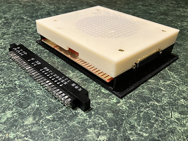
Anyway having built up a couple of PCBs which are working (apart from the USB connectivity) I have drawn up and 3D printed a little case so the PCB can be used as a standalone computer. A simple instrument case comprising top and bottom halves with a separate front panel having cutouts for keyboard and power / interface cables.

The majority of external connections (as well as the LEDs) are placed around the perimeter of the PCB so I've allowed access to these, leaving them flush or slightly recessed where possible to prevent unused connectors from jutting out. At the rear the JAMMA edge connector can be used or not, I've also left a slot for the RGB video cable and fitted a right angle, 6 way header to the PCB to allow horizontal connection.
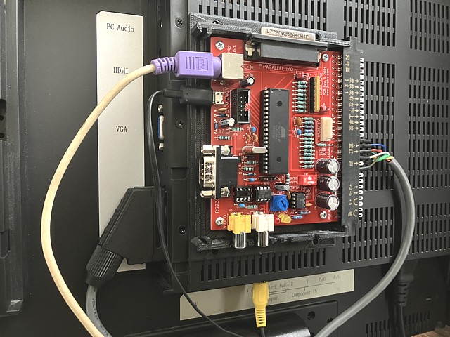
The lower half of the case has an external mounting flange for fixing within a cabinet as well as 75mm VESA mounting holes to allow it to be affixed to the back of an LCD SCART TV / Monitor as shown here.
The lower case can be used on its own just as a mounting plate or fully enclosed with lid and front panels fitted. The lid includes a slotted grille for ventilation and could also incorporate a small speaker but for standalone use I prefer to connect the low level, RCA audio output to the monitor audio input and use the monitors internal speakers.
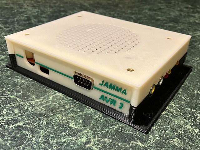
Although not intentionally copied from other products, due to its overall shape and size the finished case does resemble a typical multi game JAMMA PCB so I've nicknamed this one 'Aunt Dora's Box'...
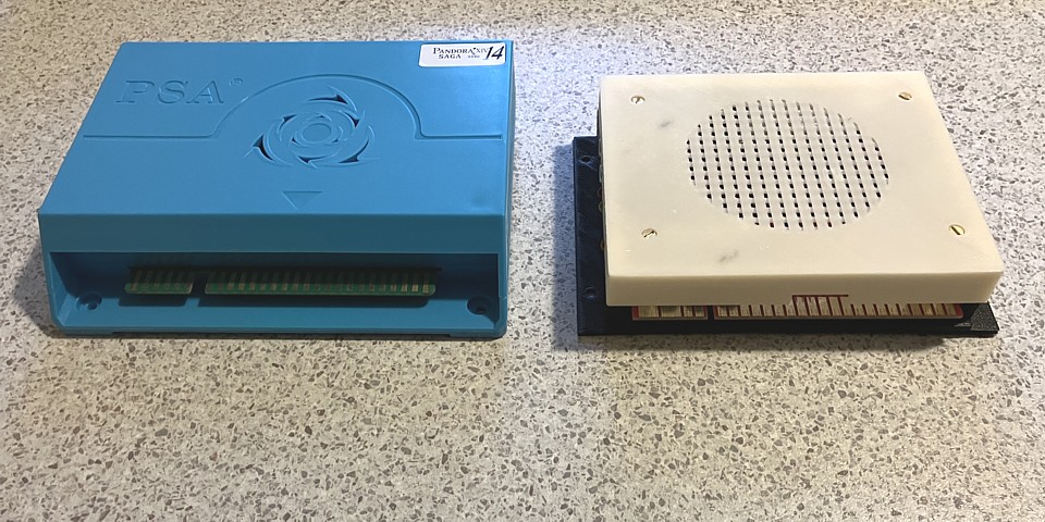
Ok, now that I have a couple of JAMMA-AVR2 PCBs made up and working it's time to see if I still remember how to write some little retro games in BASIC. Browsing the AVR Chipbasic2 and CB2 micro project pages there are already a number of example programs which will run on my version of the hardware and, with a little adaptation can be controlled by joystick and buttons connected to the JAMMA interface.
A couple of favourites are a little program called Racer, this vertical scrolling car driving game reminds me of one I programmed for the Ohio Superboard in about 1980. My program had no colour or sound (of course) but apart from the randomly generated winding road sections mine had occasional straight sections where oncoming cars hurtled towards you and had to be avoided.
The other little gem is a Tic Tac Toe game which reminds me of probably my earliest memory of an interactive electronic game. I saw and played 'noughts and crosses' with a machine at the Powerhouse Museum (then known as the Technological Museum, in Ultimo) as a kid in the early '70s. This early computing technology made a huge impression on me at the time and would steer my future career choices.
So for the sake of nostalgia I'll attempt to write a BASIC game or two and, reading the programming manuals for the AVR Chipbasic2 OS I'm inspired to have a go at everyone's favourite block stacking game. The 16 colour graphics and sound along with the ability to display text and blocky graphics characters seems to lend itself to this purpose. I'll call the game Blocky, which seems appropriate.
As well known versions of the game are always accompanied by a music score I'll begin with the music and attempt to program a recognisable tune for the inbuilt sequencer which runs in the background as the program is executed. But first I need to know which note values correspond with which musical notes so I'll write a little program to test them out.
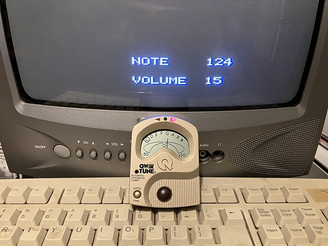
Here I'm using a little instrument tuner with a program to select and play any note value on the system. The little square is indicating the note is a C while the needle display and red arrow are showing the pitch is a little on the high side - but close enough for retro! This would be the nearest value to high C on a piano.
After testing every note value in that range 64 - 128 and marking the corresponding musical notes I'll use those values in an array to define a brief tune. I'm not great at reading sheet music but have located a chart of piano notes for the desired tune, see link below. I don't think the system will play chords and the additional notes would require too much data space anyway so I will try to capture the melody, sticking to the higher scales.
Having stored the note values and durations between notes in the array (a total of 107 notes occupying 27 BASIC lines of array values) and using the BASIC command PLAY to set the sequencer in motion I'm amazed to hear a faithful rendition of the intended tune. It sounds great but I can imagine it will become incredidbly irritating when repeated over and over during gameplay. Oh well, it can always be turned down...
On to the graphics and there are 7 possible shapes each comprising 4 individual blocks, with 4 angles of rotation so I'll store the relative position of each block for every combination in another array. The relative X and Y positions are numbered 0 to 3, avoiding negative numbers as the '-' symbols would take up extra space in the BASIC lines defining the array data.
For every shape / rotation value one of the four blocks is in position 1,1 relative to X and Y values so I only have to store the positions for the other three blocks in each case. That takes 14 lines of BASIC, another 2 lines to define the characters to draw smaller versions of the shapes in the 'next shape' preview area.
There is also one line to define a sprite which will be used for potential collision detection and one to contain the Ascii characters to draw the title BLOCKY with individual background colours so the array values take up the first 45 lines of BASIC code. That leaves exactly 50 lines of the 95 in a single pogram slot to write the actual program, which I'll include below:
Apart from moving the shapes, avoiding potential collisions and detecting when the shape has 'landed' on the pile the program determines scores and stores the high score value to the MCUs internal EEPROM at game end. One point is awarded for every shape placed and any layers which have been filled are then removed. Ten points for a single layer cleared or more if multiple layers are filled in a single pass.
To keep the mathematics simple and save additional lookup tables the points awarded for clearing layers are 10 x (the number of layers cleared)squared so 10, 40, 90 or 160 points for 1 to 4 layers in a single pass. Along with the music track a tone is heard when each shape is placed and another tone of increasing pitch as each full layer is cleared. At 20 layers the speed of the shapes falling and tempo of the background music is doubled.
The total program size is one program slot of 95 BASIC lines including music and graphics data or about 3k Bytes of program memory. Not bad I think for a game which involves a lot of calculations.This version uses keyboard input left, right and down to move the shape and L_Shift / L_Ctrl to rotate so this program should also run correctly on original AVR Chipbasic2 and CB2 Micro computers.
blocky.txt Block stacking game v1 BASIC program listing
The next version will accept input from JAMMA connected joystick and buttons which will most likely require some subroutines in an additional program slot so I may take the opportunity to also write an arcade style attract mode and 'press start' routine rather than having the program terminate at game over. If / when I get around to doing that I'll add a link to that version as well. Meanwhile here is a little video of the gameplay.
My JAMMA-AVR2 retro computer has been working well so far, one feature I've added to my second revision PCB which has yet to be sorted out is the provision for USB connectivity. The original RS-232 interface works perfectly for loading and storing programs via a PC running terminal software but that requires a computer which also has an RS-232 serial port or alternatively an in-line RS-232 to USB converter.
I had already included a micro USB connector on the PCB to allow for powering independant of the JAMMA connector so an integrated USB data connection seems like a worthwhile addition and can be implemented using a MCP-2221A interface IC. In the Rev. 2 PCB layout I found just enough space to include the 14 pin DIP, through hole version of the IC. Unfortunately when I fully assembled and tested the new PCB the USB connection did not seem to be working correctly.
Following an initial sound to indicate the PC had detected a new USB device, an error message would show the device was not recognised or had failed. To investigate further I decided to begin with a second, empty PCB populated with only the USB connector and interface IC as well as the +5V filter and bypass capacitors. Even without the microcontroller installed the symptom was the same so there is some fundamental problem with my implementation of the IC.
After much reading and some experimentation I did find a number of issues; firstly the IC data sheet recommends a smoothing capacitor of 0.47uF across the internally regulated 3.3V USB supply pin 11, to ground pin 14. Also even though an internal pullup resistance is apparently included on the /Reset input pin 4, an external 10k Ohm pullup resistor is recommended to +5V pin 1. I have tried adding both of these components on the solder side of the PCB.
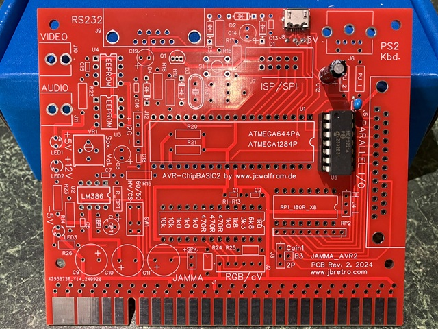
A more serious issue appears to be the distance and routing of the D+ and D- data signals to the micro USB connector. As the data is carried by a differential pair the length and proximity of the tracks should be closely matched as well as avoiding sources of interference such as nearby clock signals. As the location of the IC in the only available space was not ideal my layout was flawed including non matched track distance and signals crossing over requiring an added via.
The only way to test an improved routing at this stage is to cut the D+ and D- tracks at both ends and then run a pair of wires directly from IC to USB connector, which I have done on the solder side. It's not perfect as the wires are still connected via through holes to the surface mount USB connector but the result is promising with the device being recognised and added as a COM port at least some of the time.
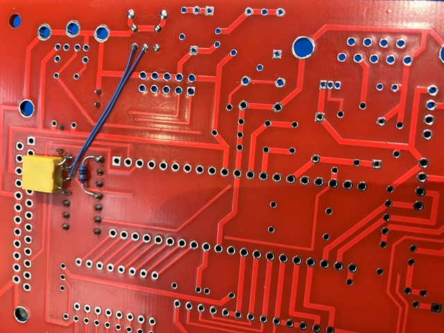
The next step is to try that on the fully populated PCB. To match the length and spacing of the data signals as closely as possible I've used a piece of ribbon cable, the third wire is a ground connection to the IC directly from the USB socket ground. Although that works at first the connection is still not perfect and the port frequently cuts in and out on the PCs device manager hardware listing.
The issue with a differential signal is any mis-timing between the two halves will present as a 'glitch' on every transition causing data errors and corrupted device ID. Having matched the length of wires as closely as possible (without a more accurate redesign of the PCB layout as yet) the errors should be fairly minimal, mainly affecting the high speed handshaking rather than the low speed serial data.
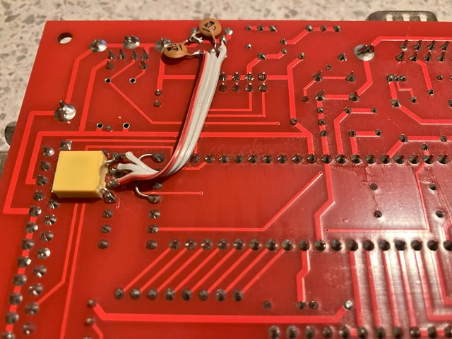
To try and supress any glitches which may be causing errors I've added a small capacitance, 47pF to both data lines. Although not recommended that does work and results in a reliable USB data connection given the less than perfect PCB layout. The more permanent solution will be yet another PCB revision which places a surface mount version of the MCP2221A interface IC right next to the USB socket with an almost direct connection of the D+ and D- signals.
In the previous installment of my JAMMA-AVR2 computer project the system was working well apart from some issues with my attempt to add USB connectivity. The initial version of the computer worked perfectly but only had an RS-232 interface for loading and saving programs while modern computers usually have only USB ports available. Although an external adapter could be used it made sense to include a USB interface to make program loading and storage more convenient.
My second revision PCB included a MCP2221A interface IC which should have worked but seemed to be failing to connect, I suspected less than ideal placement within the PCB layout and longer paths for the differential data signals may have been the main issue so my next step was to draw up a third revision PCB which utilised a smaller, SMD version of the interface IC placed right next to the USB connector to eliminate any problems with the differential data signal paths.
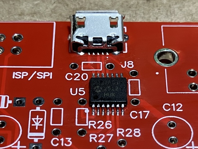
The revision 3 PCB was expected to work perfectly, to my surprise there still seemed to be a similar problem. What I eventually found to be causing the connection issue was unexpected - the USB socket had some flux residue underneath which was causing a current drain and loss of data signal. After removing, cleaning the residue and fitting a new socket using a more suitable flux the connection issue was resolved.
In the initial version the USB socket was the only surface mounted component and was only added to provide a convenient power source for the PCB, the data pins of the connector were unused. As a power input the socket worked fine so the method of placement didn't come into question. Only when the USB interface was added to the design did the method of soldering and choice of flux become critical.
The PCB was designed to use through hole components for simplicity however the micro USB power socket was not available as a through hole component so became the only surface mounted item on the board. I don't use flux with through hole components but for hand soldering the pins of the USB socket, with a 0.65mm pitch some flux would be required to prevent the conventional solder from bridging the connections.
The flux which I initially used was an RA type (Rosin Activated) and after soldering I cleaned away the residue however some must have been washed underneath the body of the connector, bridging between data pads and power or ground. Unfortunately the residue from this type of flux is both corrosive and conductive so if not completely removed can cause circuit faults as well as long term track / pad damage.
A more suitable flux for this type of soldering is a 'no clean' type which after heating leaves an inert residue. It can still be cleaned away but is not so critical if small deposits remain in difficult to reach places. After fitting the USB socket as well as the SMD interface IC to the latest PCB revision, using the 'no clean' flux the USB interface now works reliably.
One other change to the Rev. 3 PCB was to relocate the ISP/SPI header close to the edge so a right angle header plug could be fitted. This is a more convenient position for use with a dataflash extension module (similar to a USB flash drive but using the ISP interface of the micro controller) to save and load programs without the need for a connected PC.
The original circuit design by Joerg Wolfram (see link below) included an extension for the dataflash module based on an AT45DB081B flash memory IC. Although that IC is no longer produced (some stocks are still available from online sellers), later 'D' or 'E' versions are also available in a smaller 8 pin SMD package so I tried making up a PCB to suit the later revision ICs.
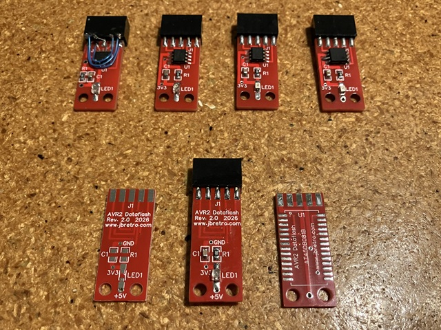
After correcting a slight error in my first design (hence the bodge wiring) and trying both AT45DB081 'D' and 'E' version ICs I concluded these were not fully interchangeable with the earlier 'B' version as they would format but not show any available memory blocks. Reverting to the AT45DB081B of the original design I made up a new PCB, placing the larger 28 pin SMD IC on the bottom side of the PCB to keep the overall size to a minimum.
That works as expected and can store up to 256 programs within its 1 Megabyte capacity - each program slot on the system equates to around 3 kiloBytes of memory. I also drew up and 3D printed a small housing for the dataflash PCB, keeping the green LED visible to indicate activity and also adding a keyway to ensure the module is inserted into the 10way ISP header connector with the correct orientation.
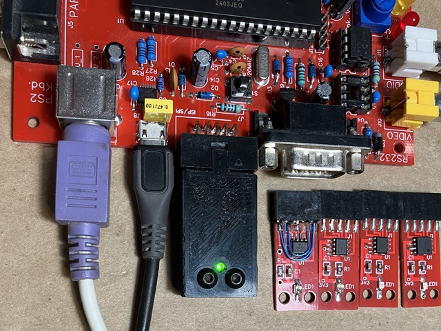
So the latest revision PCBs are fully working with both RS232 and USB connectivity as well as a dedicated flash memory option for storage and loading of programs. That pretty well completes the hardware development, meanwhile I have also been writing some 'new' BASIC game programs to run on the system. And no system would be complete without a clone of the most iconic space shooter ever...
skinny.txt Skinny Vaders game v1 BASIC program listing
With the PCB now fully working I'll 3D print an enclosure to complete the package. My previous design worked well so the new case will be the same, with one additional opening in the front panel for the repositioned ISP / dataflash port. So far I have two 3D printed enclosures; the prototype which I printed on my own FDM printer was successful so I also sent the files away for SLA printing.
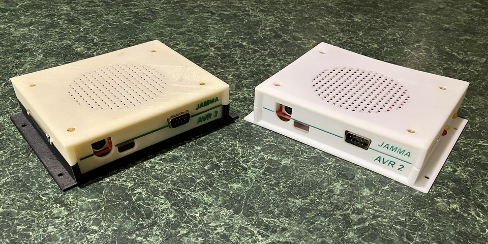
Although the finish of the SLA printed version was superior, the parts did have a tendency to warp due to the large flat areas without internal bracing so my design was ultimately better suited to FDM printing with the flat side of each part facing the print bed. I'll print another enclosure for the latest PCB using a bit of colour to set it apart from the previous revisions.
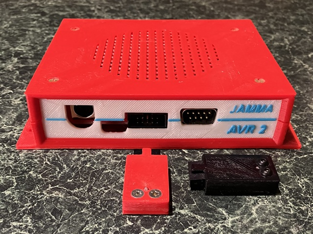
One disadvantage of the fully enclosed PCB is limited access to internal switches and controls - I could just add some carefully placed holes to the top cover to allow adjustment of the switches and volume control but not wanting to spoil the appearance I'll reposition the reset switch and volume Pot. to the underside of the PCB, making some small holes in the bottom panel instead.
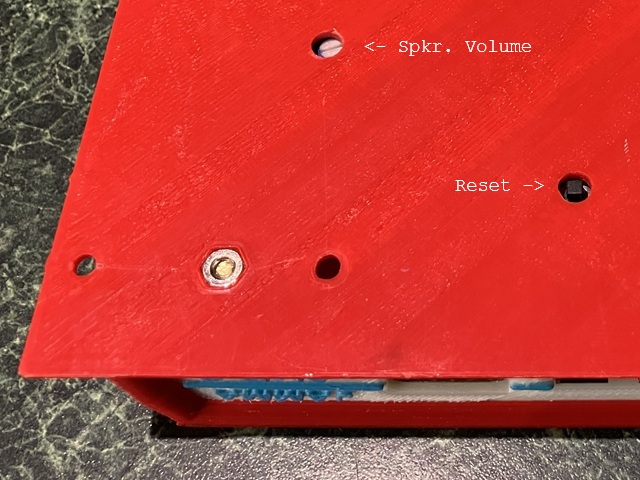
The reset switch is handy when using the serial loader software and saves having to power cycle the PCB. The volume Pot. is only needed to set the Max. volume level of an external speaker (e.g. when using the JAMMA interface and the +12V supply is present) and doesn't affect the low level audio output. The internal volume level can also be adjusted within software.
My JAMMA-AVR2 PCB project is nearing completion with my latest revision now fully sorted and working. Along the way I have learned some new tricks with PCB design and layout and even some do's and don'ts about integrating SMD components into the design. I'm calling the PCB finished but that still leaves room for development of new extensions and interfaces to exploit the potential of the ATmega micro controller at its centre.
I have already made use of the parallel I/O port to read one player Joystick and button inputs from the JAMMA interface but the ATmega 644 also has an inbuilt Analog to Digital converter (ADC) and multiplexer (ADMUX) which can read a 10 bit conversion of an analog Voltage applied to any of its 8 parallel input bits. This means the parallel interface could be further extended to read simultaneous input from two analog joysticks, each with two buttons.
The potential for some new, 2 player retro games using either paddle controllers or analog joysticks immediately comes to mind. I do have one pair of Atari paddle controllers but with only 1 axis and 1 button each this would limit the options (unless two pairs were used for 4 player games - think Atari Warlords, for example). I also have two, vintage PC type analog joysticks in metal cases, each with 2 buttons and standard 15 pin D connectors as per early PC analog joystick ports. Perfect!
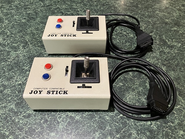
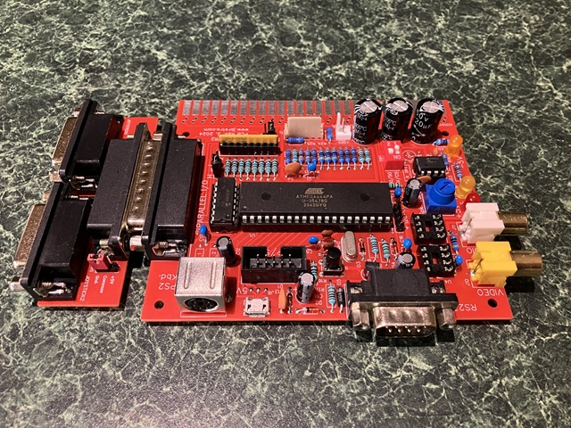
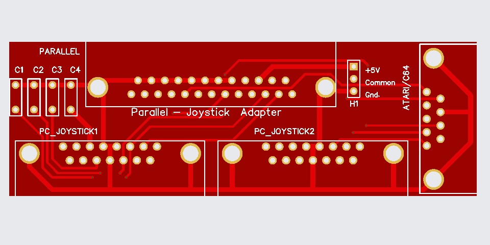
So, I've drawn up a small adapter PCB which plugs into the 25 pin parallel I/O connector and has two 15 pin D connectors for PC style analog joysticks. These should contain a 100k Ohm linear potentiometer for each axis as well as up to two button switches. In a PC joystick port the common side of the potentiometers connects to +5V but as the parallel inputs on my PCB are already configured with a 10k Ohm pullup resistance the potentiometers will be used to form a Voltage divider to ground.
The result of an ADC(n) instruction for a given input will be a number somewhere between 0 and 1024 which varies according to the position of the joystick axis. As the Voltage divider comprises a 180 Ohm series resistance, 10k Ohm pullup and 0 - 100k variable load to ground the actual result is not linear and never reaches the upper or lower limits so some scaling will be required once the centre and limit values have been measured for a given joystick.
I've written a BASIC program to calibrate the two joystick inputs and display their position after scaling. Although the program is fairly long, once the characteristics of each Joystick have been determined the scaling values can be used in a game program without the need to re-calibrate each joystick every time. So the 'Joy Stick' calibration program is a standalone utility rather than a routine to include within a game program.
joystick.txt Joy Stick calibration utility v1 BASIC program listing
I have also found it helpful to add a small capacitance to prevent dithering of the analog joystick reading, around 1 uF across each axis which I will incorporate into the next PCB revision. I'll even add a third joystick connector for Atari / C64 style joysticks which can be read in the same manner as the JAMMA control inputs, being a simple switch to ground for each axis or button input. This allows the PCB to be used either within a JAMMA wired cabinet or as a standalone 'console'.
The next step will be to write some BASIC games which utilise the various input options of the computer, single / 2 player using keyboard, joystick / JAMMA or analog inputs. the possibilities seem endless. One title which immediately came to mind was a 'bronze age' arcade and console classic which originally used just a single analog control input so I'll begin with my tribute to that game. My initial version is for keyboard input but will add joystick / JAMMA and analog input options in the next version.
stuntr.txt Stunt Rider game v1 BASIC program listing
My latest PCB extension for the JAMMA-AVR2 computer has arrived, this one is Revision 2 of the Analog Joystick interface which adds a 9 pin connector compatible with Atari / C64 'simple' joysticks. I hesitate to refer to those as 'digital' joysticks as that would imply some measure of complexity - in reality each axis of these is a simple switch to ground so the control is either ON or OFF. The same applies to the JAMMA standard controls so the inputs on the 9 pin connector are wired in parallel to the Player 1 JAMMA control inputs.
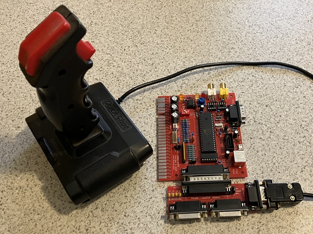
Likewise the two PC Analog joystick inputs connect to the same 8 bit parallel inputs on the micro controller, the difference is in the software which has the ability to read either a binary input level or a 10 bit analog to digital conversion of the Voltage at each input. Apart from the obvious difference between an analog signal and a simple binary switch closure, configuring the 8 input bits for analog input also allows the potential for two player controls -
Each analog joystick axis occupies a single input rather than two binary input bits i.e. X and Y position rather than Up, Down, Left and Right. So the analog inputs are configured for two joysticks, each with up to 2 buttons while the JAMMA / Atari / C64 inputs are configured for a single joystick with up to 4 buttons e.g. coin/select, start, button1 and button 2.
The downside is the need for calibration of the analog joystick input range but as this is fairly consistent for a given joystick a separate calibration program allows the scaling factors to be determined and these values can be included in a game program without the need to re-calculate each time. The available space within each program slot is limited however secondary programs can be called as subroutines, for example a joystick calibration program could be called as part of the main game program.
I am yet to write any multi player games for the system and the gameplay will need to be very simple to keep the program size within a few kilobytes but early arcade style games with analog controls should be possible, anything from Pong through to Speed Race for example. My first attempt at using just a single axis analog input will be the next revision of my tribute to the classic motorcycle stunt game, Stunt Rider.
The idea behind the gameplay is to accelerate gradually up to the correct speed to jump an increasing number of buses. Too fast, too slow or too much aceleration will cause a crash. I began with keyboard only controls so the trick is to use the down button (= accelerate) or up (decelerate) repeatedly or in short bursts to avoid reaching a high speed too quickly. The same approach works fine for a JAMMA or Atari style joystick, accelerating or slowing in increments.
Although the original plan was just to work towards an analog joystick control the keyboard method works surprisingly well once you get used to it. Nonetheless I have revised the program, adding both JAMMA / Atari joystick input ability as well as analog joystick option using the Y axis of joystick 1 for the throttle control. I have even designed and 3D printed a custom analog controller just for the Stunt Rider game.
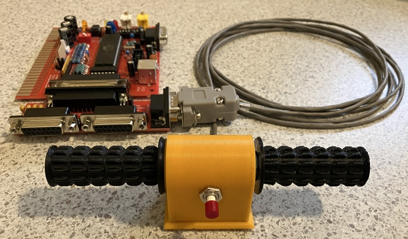
Well, I already had the motorcycle hand grip style potentiometer knob which I designed for my recreation of the Dick Smith kit game based on the General Instrument AY-3-8760 IC. All that was needed to make a standalone controller was the centre housing for a 100k Ohm pot. and 1 pushbutton, the left hand grip (which is part of the same 3D object, just switching filament colour during the print process) and a bottom cover.
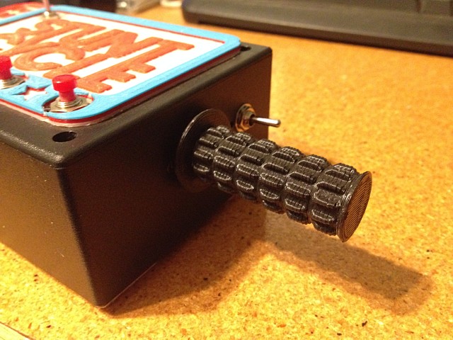
- although the new controller could be screwed to a control panel to make a mini version of the arcade machine - just a thought... Aaanyway, another example of linking programs by calling a second program as a subroutine of the first; is a little 'Arcade Menu' program which I wrote in BASIC a while back. It uses the JAMMA joystick and button inputs to select a game from a menu screen.
I have mostly been writing arcade style mini games to make use of the computer's JAMMA control interface but one limitation was the computer's own main menu screen which can only be navigated by keyboard input. A single program can be set to autoload upon boot but to change from one program to another would require a connected PS2 style keyboard.
Cue the Arcade Menu program which can be set as the auto-loaded program on power up, presents a choice of mini games and even my CRT test program from up to seven menu choices (the computer has a total of 8 program slots so 7 is the maximum number which can be available at once, plus the menu program). It plays a little theme tune and even has a coin / credit option - just for fun of course.
At 'Game Over' a RETURN statement added to each game program resumes the Arcade menu program. Music volume and credits are retained in the computer's internal EEPROM while individual games also have the ability to retain high scores. One issue I encountered when adapting the games to work under the menu program was the CALL - RETURN function did not seem to work when nested with GOSUB - RETURN statements within the sub programs.
Fortunately there weren't too many subroutines in the small game programs and a workaround was possible; some could be changed to simple GOTO instructions and the return line number stored as a variable if required. Apart from my own games I have adapted some of the examples from the original project pages to work with joystick and button controls as well as my menu program.
The game 'RACER" was a simple example program from the jcwolfram.de site to which I added joystick input as well as a limit of 3 lives instead of the infinite repeat. The game also featured an example of the high score save routine which I have since incorporated into some of my own games, each saving their high scores into a unique location within the computer's internal EEPROM.
I even included a 'high score clear' function into my Arcade Menu program, the input combinations for that are noted as comments within the BASIC program. I'll include a brief video of the menu program with the currently featured games below.
To be continued...
JAMMA_AVR2 PCB specifications
| Made | 2024 - 2026 |
| CPU | Microchip ATmega644PA or 1284P @ 20 MHz |
| RAM | 4kByte (644PA), 16kByte (1284P) (expandable via parallel I/O) |
| FDD | None |
| Ports | JAMMA, Serial RS232, USB, Parallel, I2C, SPI |
| O/S | AVR-ChipBasic2 by jcwolfram.de |
| Display | 16 colour, 30 x 23 characters displayed |
| Sound | Mono (notes in 2 tones, noise) |
| Monitor | Monochrome composite or RGBs, 15kHz; 50/60Hz switchable. |
| Keyboard | PS2 standard keyboard port |
| Speakers | Mono speaker out, max 1W approx @8 Ohms |
Web Resources (External Links) -
AVR-ChipBasic2 - www.jcwolfram.de
CB2 micro - SV3ORA website qrp.gr/cb2
CB2 Microcomputer channel - YouTube
Dance of the Sugar Plum Fairy by Tchaikovsky - Piano Letter Notes
All images and text on this website are Copyright.
Contact: jbtech at telstra dot com